
A compliant Class B Pt100 thermometer bought in Southport and one bought in Singapore will each match the same defined curve to within ±0.3 °C at 0 °C, without any calibration passing between them. That interchangeability is the work of one document: IEC 60751, the International Standard for industrial platinum resistance thermometers. Anyone specifying, buying or calibrating platinum sensors deals with its consequences daily, often through second-hand labels such as "Class A" or "1/10 DIN" whose meaning has shifted over forty years of revisions.
This article sets out what the current edition, IEC 60751:2022, actually says: the resistance to temperature relationship, the tolerance classes and their ranges of validity, and how the familiar fractional "DIN" tolerances now fit within the standard rather than outside it.
The standard at a glance
IEC 60751:2022 (Edition 3.0, published January 2022) specifies the requirements for industrial platinum resistance thermometers and platinum temperature sensors over the range −200 °C to +850 °C. In the UK it is published as BS EN IEC 60751:2022.
The standard distinguishes between two things that are often conflated:
- Platinum resistors (the sensing elements, sometimes called detectors), made from platinum wire or film embedded in glass or ceramic.
- Thermometers, the complete assemblies: one or more platinum resistors in a protective sheath, with internal connecting wires and external terminals.
Tolerances are published for both, and they differ. A sensing element meeting a given class does not automatically produce a finished thermometer meeting the same class; since the 2008 edition, the complete thermometer has had to meet its tolerance at the terminals, rather than the element alone at its connecting points.
All temperatures in the standard are expressed on the International Temperature Scale of 1990 (ITS-90). The standard applies to sensors with a mean temperature coefficient between 0 °C and 100 °C of α = 3.851 × 10⁻³ °C⁻¹. What alpha is, and why it takes this value, is covered in a companion article: What is Alpha?
How the standard evolved
The first edition, IEC 751, appeared in 1983 and was amended in 1986 and 1995. The 1995 amendment mattered most: it revised the resistance to temperature relationship to align industrial platinum thermometers with ITS-90, following a review of the state of industrial platinum resistance thermometers generally.
Why the change to ITS-90 mattered: ITS-90 replaced the earlier International Practical Temperature Scale of 1968 (IPTS-68) and assigned slightly different numerical temperatures to the same physical states. The platinum element itself had not changed, but its measured resistance now had to correspond to temperature on the new scale. Revising the IEC coefficients kept the standardised resistance–temperature relationship consistent with ITS-90, avoiding small systematic differences between sensor calculations and calibrations traceable to the new scale. The practical effect is explained further in What is Alpha?
The second edition was published as IEC 60751:2008 in July 2008. The change from "IEC 751" to "IEC 60751" was administrative, not technical: it came from the IEC-wide renumbering introduced in 1997, which added "60000" to the number of every existing IEC standard, rather than from the 2008 revision itself. The technical content of the second edition introduced the tolerance class scheme still in use, separated element tolerances from thermometer tolerances, and for the first time gave different ranges of validity for wire-wound and film sensors.
The third and current edition, IEC 60751:2022, was published in January 2022. Its significant technical changes are:
- The equations defining resistance versus temperature are now the normative specification; the familiar numerical resistance tables cease to be normative and appear in Annex A for information only.
- A new clause on compliance and requirements: suppliers are responsible for testing and proving conformity before a device reaches the user.
- A modified tolerance acceptance test.
- An expanded marking system that accommodates special tolerance classes and special temperature ranges of validity (of which more below).
- A revised vibration test method.
- A new cold seal test, added as an additional type test.
The resistance to temperature relationship itself did not change in 2008, and it did not change in 2022. It has been stable since 1995.
The resistance to temperature relationship
The standard defines resistance as a function of temperature using the Callendar-Van Dusen equations.
For the range −200 °C to 0 °C:
R(t) = R₀ [1 + At + Bt² + C(t − 100 °C)t³]
For the range 0 °C to 850 °C:
R(t) = R₀ (1 + At + Bt²)
where R₀ is the resistance at 0 °C. The coefficients have held the same values since the 1995 amendment:
| Coefficient | Value since 1995 (current) | Value before 1995 |
|---|---|---|
| A | 3.9083 × 10⁻³ °C⁻¹ | 3.90802 × 10⁻³ °C⁻¹ |
| B | −5.775 × 10⁻⁷ °C⁻² | −5.802 × 10⁻⁷ °C⁻² |
| C | −4.183 × 10⁻¹² °C⁻⁴ | −4.2735 × 10⁻¹² °C⁻⁴ |
Note: Under the 2022 edition it is these equations, not the printed tables, that define a conforming sensor. Anyone still working from photocopied resistance tables should be aware that the tables are now informative only, though values calculated from the equations will of course agree with them.
Tolerance classes in the current edition
IEC 60751:2022 publishes tolerance classes in two tables: Table 1 for platinum resistors (elements) and Table 2 for complete thermometers. The tolerance formulas are identical across the two tables; what differs is the temperature range over which each class is valid, and those ranges depend on whether the sensor is wire-wound or film.
Note: TDI manufactures wire-wound PRTDs only. Thin-film tolerances are shown below for reference, while IEC 60751 demonstrates that wire-wound elements maintain specified tolerance classes over consistently wider temperature ranges.
Tolerance classes for platinum resistors (elements)
| Wire-wound class | Valid range (°C) | Film class | Valid range (°C) | Tolerance (°C) |
|---|---|---|---|---|
| W 0.1 | −100 to +350 | F 0.1 | 0 to +150 | ±(0.1 + 0.0017 |t|) |
| W 0.15 | −100 to +450 | F 0.15 | −30 to +300 | ±(0.15 + 0.002 |t|) |
| W 0.3 | −196 to +660 | F 0.3 | −50 to +500 | ±(0.3 + 0.005 |t|) |
| W 0.6 | −196 to +660 | F 0.6 | −50 to +600 | ±(0.6 + 0.01 |t|) |
|t| is the temperature in °C without regard to sign.
Tolerance classes for thermometers
| Class | Valid range, wire-wound (°C) | Valid range, film (°C) | Tolerance (°C) |
|---|---|---|---|
| AA | −50 to +250 | 0 to +150 | ±(0.1 + 0.0017 |t|) |
| A | −100 to +450 | −30 to +300 | ±(0.15 + 0.002 |t|) |
| B | −196 to +600 | −50 to +500 | ±(0.3 + 0.005 |t|) |
| C | −196 to +600 | −50 to +600 | ±(0.6 + 0.01 |t|) |
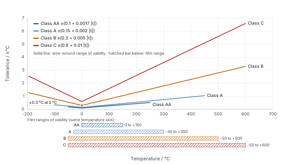
Two points deserve attention.
First, the ranges of validity are the substance of the classification, not a footnote. Current Class A retains the tolerance formula of the old (pre-2008) Class A, ±(0.15 + 0.002 |t|), but now carries construction-dependent ranges of validity rather than applying across the board. Class AA, introduced in 2008, is a tighter class again, at ±(0.1 + 0.0017 |t|), with a narrower range still. A film Class AA thermometer, for example, carries no class tolerance at all below 0 °C or above 150 °C. Outside the range of validity, the standard makes no promise on the sensor's behalf.
Second, wire-wound sensors have wider ranges of validity than film sensors in every class. The standard states that these ranges are based on working experience with the two constructions. The reasons behind that difference, and what it means when choosing between the technologies, are discussed in Why Wire Wound?
Note: Under IEC 60751:2022, thermometers with a tolerance class better than Class B must use a 3-wire or 4-wire connection, with 4-wire recommended, because with only two wires the lead resistance sits inside the measurement. A 2-wire thermometer therefore cannot be declared conforming to Class A or Class AA.
Fractional tolerances: where "1/10 DIN" came from, and where it now lives
For decades, users needing better than Class A interchangeability have specified fractions of the Class B tolerance: 1/3 DIN, 1/10 DIN and so on. The "DIN" label survives from DIN 43760, the German standard that predated international harmonisation. DIN 43760's platinum content passed to DIN IEC 751 in the 1980s (its 1987 revision covered nickel elements only), and platinum sensors in Germany have been governed by DIN EN 60751 ever since. The label outlived the standard; the tolerance it refers to is the Class B formula, ±(0.3 + 0.005 |t|).
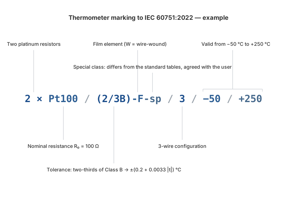
Special tolerance classes agreed between supplier and user are not new to the 2022 edition — the standard has long left room for departures from the published tables by agreement. What the 2022 edition added was clarity: an expanded marking system, formalised in Clause 5.2.3.2, that recommends special classes be constructed as multiples or fractions of the Class B tolerance, and requires such thermometers to be marked with the suffix "-sp" so the departure from the standard tables is visible on the device itself.
A marking under the 2022 scheme reads, for example:
2 × Pt100 / (2/3B)-F-sp / 3 / −50 / +250
decoding as: two Pt100 resistors, tolerance two-thirds of Class B (±(0.2 + 0.0033 |t|)), film element, special class, 3-wire configuration, valid from −50 °C to +250 °C.
What a fractional tolerance actually promises
Here it is worth slowing down, because fractional tolerances are widely misread, and two distinct things travel under similar names. A commercial "1/10 DIN" specification, as normally sold, is a statement about interchangeability at 0 °C only — a tight selection of R₀. It is not automatically the same as an IEC special class such as (1/10B)-sp, which under Clause 5.2.3.2 means one-tenth of the complete Class B formula, ±(0.03 + 0.0005 |t|), held across a declared range of validity — a materially stronger claim. TDI specifies its fractional tolerances as R₀ selections, in the traditional commercial sense:
| Interchangeability at 0 °C | Traditional commercial designation |
|---|---|
| ±0.05 % of R₀ | 1/2 Class B |
| ±0.03 % of R₀ | 1/3 Class B |
| ±0.02 % of R₀ | 1/5 Class B |
| ±0.01 % of R₀ | 1/10 Class B |
Away from 0 °C, the agreement between sensors opens out again, because each sensor's temperature coefficient differs slightly from the nominal curve. For TDI detectors this spread is governed by an alpha uncertainty of ±3 ppm. The practical consequence: a "1/10 DIN" sensor selected this way is roughly ten times better than Class B near 0 °C, but it is not ten times better at 300 °C — tight R₀ selection alone cannot guarantee that, though a verified special tolerance band or an individual calibration can. The BIPM's guide on industrial platinum resistance thermometers makes the same point: reduced tolerance bands of this kind conventionally refer to the R₀ value only.
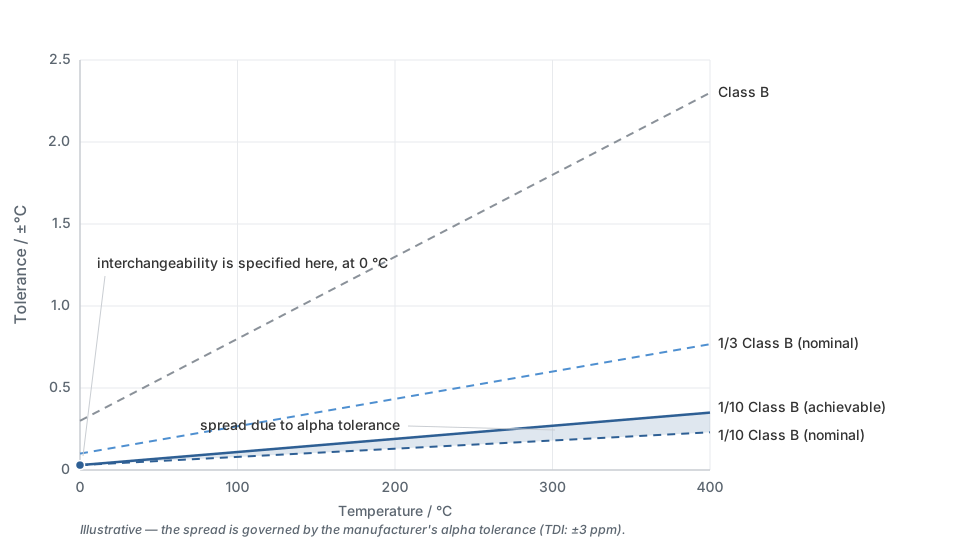
For applications that genuinely need small uncertainties across a working range, the honest route is not an ever-smaller fraction of Class B. It is an individually calibrated sensor with its own coefficients. The standard itself says as much: relationships with uncertainties below 0.1 °C call for individual calibration and a more complex interpolation equation, and are outside the scope of the document.
Other standards you will meet
ASTM E1137/E1137M is the American specification for metal-sheathed industrial platinum resistance thermometers, covering −200 °C to +650 °C. It uses the same Callendar-Van Dusen equation and coefficients as IEC 60751 but defines two tolerance grades, A and B, with different formulas (Grade A: ±(0.13 + 0.0017 |t|); Grade B: ±(0.25 + 0.0042 |t|)). An ASTM Grade B thermometer is not the same as an IEC Class B thermometer, and the two should not be interchanged in specifications.
JIS C 1604 is the Japanese standard. Japan introduced an IEC-based Pt100 relationship in the 1989 revision, though the older JPt100 curve remained available at that stage; the 1997 revision brought JIS C 1604 fully into conformity with the revised IEC relationship. The current edition, JIS C 1604:2013, continues that alignment. JPt100 (α = 3.916 × 10⁻³ °C⁻¹) is no longer standardised, though instruments still offer it as a configuration option for legacy installations.
What this means when specifying a sensor
The tolerance class system answers one question well: how closely will an uncalibrated sensor, taken from stock, agree with the published curve, and over what range? When specifying, that translates into a short list of checks:
- State the class and confirm its range of validity covers your operating range, for your element construction (W or F).
- For anything better than Class B, specify 3-wire or preferably 4-wire connection.
- Keep measuring current low enough that self-heating stays small; the standard requires self-heating to stay within 25 % of the tolerance value, and states that the measuring current is usually not more than 1 mA for a 100 Ω wire-wound platinum resistor.
- If you are quoting a fractional Class B tolerance, be clear with your supplier whether it is a traditional R₀-only selection or a full-range IEC special class, and what either promises away from 0 °C.
- If the application needs better than the classes offer, calibrate the individual sensor rather than chasing tighter fractions.
To see what each element class permits at your operating temperature — and to check a measured resistance against the classes — use our RTD element tolerance calculator.
A tolerance class is a statement about interchangeability, not about the performance of your particular sensor in your particular installation. Immersion, self-heating, thermal gradients and drift are all outside its scope. The class tells you where a sensor starts; calibration and good measurement practice determine where it ends up.
IEC 60751:2022 can be purchased from the IEC webstore; the UK implementation, BS EN IEC 60751:2022, is available from BSI.
Further reading
- IEC 60751:2022, Industrial platinum resistance thermometers and platinum temperature sensors, Edition 3.0, IEC, January 2022
- BIPM Consultative Committee for Thermometry, Guide on Secondary Thermometry: Industrial Platinum Resistance Thermometers (bipm.org)
- ASTM E1137/E1137M-08(2020), Standard Specification for Industrial Platinum Resistance Thermometers
- JIS C 1604:2013, Platinum resistance thermometers
- What is Alpha? and Why Wire Wound? on this site